
Bringing Up Zephyr RTOS on an ESP32-P4 Board
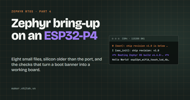
Zephyr RTOS, part 4. A bring-up on real hardware: what each file of the project does, the eight files that describe a board Zephyr has never seen, and then build, flash and monitor on the panel itself.
Parts 1 to 3 stayed away from any particular hardware. This one is all hardware: a Waveshare ESP32-P4-WIFI6-Touch-LCD-4B, a dual-core RISC-V ESP32-P4 with 32 MB of flash, 32 MB of PSRAM, a 720×720 touch panel and an ESP32-C6 companion chip for Wi-Fi 6.
You need the workspace from part 3, a USB cable to the board's UART bridge, and the panel's schematic. The schematic is not optional: the board files below are nothing but answers to it.
What Zephyr already has for the ESP32-P4
Two things were already in the tree, which is what keeps this job down to an afternoon:
The SoC, in
soc/espressif/esp32p4/: clocks, caches, the interrupt controller, the linker scripts. Missing SoC support would have meant weeks of work rather than a board file.A board with the same module,
boards/waveshare/esp32p4_wifi6— my panel without the display. It builds and boots today, and it is what the board folder below is copied from.
One catch: both live on Zephyr's main branch, and no tagged release carries them, not even 4.4.2, the newest at the time of writing.
The project, file by file
Everything the bring-up needs sits in one folder, six entries in total:
projects/app_template/
├── west.yml                           which Zephyr commit this project pins
├── CMakeLists.txt                     what to build, and where boards live
├── prj.conf                           which Zephyr features to switch on
├── README.md                          how to build, flash and monitor it
├── src/
│   └── main.c                         the application
└── boards/waveshare/
    └── esp32p4_wifi6_touch_lcd_4b/    the board, eight files
west.yml is the manifest from part 3, kept inside the project. It pins the Zephyr commit this board needs, because the ESP32-P4 support is not in any release, and it imports only the Espressif HAL:
- name: zephyr
  remote: zephyrproject-rtos
  # main as of 2026-09-21. ESP32-P4 support exists on main only (not in v4.4.2).
  revision: f4656a39deb70d85a8543b6f86e38211d9093597
  import:
    name-allowlist:
      - hal_espressif
The allowlist matters on this chip: importing every Zephyr module costs several gigabytes, while an ESP32-P4 build needs only hal_espressif.
CMakeLists.txt names the project, lists the sources, and adds one line that the rest of this post depends on:
list(APPEND BOARD_ROOT ${CMAKE_CURRENT_SOURCE_DIR})
That is how Zephyr finds a board outside its own tree. It points at the folder that contains boards/, not at the board, and has to come above find_package(Zephyr ...), which is where Zephyr reads it. Keeping the board inside the project that uses it is what makes the folder portable: copy it to another machine or workspace and it still builds, with nothing to register first.
prj.conf switches on logging and an interactive shell (CONFIG_LOG, CONFIG_SHELL, CONFIG_KERNEL_SHELL), plus thread names and stack usage so kernel thread list is readable, and warnings as errors to match what Twister does later. The shell is worth having from the first boot: kernel version, kernel uptime and kernel thread list answer on the console, with no code of your own.
src/main.c logs CONFIG_BOARD_TARGET and returns. That symbol is a string the build generated, so the console tells you which board file the running image came from. The shell keeps going afterwards, because it is a thread of its own and not something main() holds up.
boards/waveshare/esp32p4_wifi6_touch_lcd_4b/ is the port itself, and the next three sections are how it got there.
The board folder: copy Zephyr's, then strip it
A Zephyr board is a folder of eight files, under 4.4 kB of text in total and no C code at all. Copy the sibling board into the project:
Copy-Item -Recurse zephyr\boards\waveshare\esp32p4_wifi6 `
  projects\app_template\boards\waveshare\esp32p4_wifi6_touch_lcd_4b
Then rename the files that carry the board name, because Zephyr's hardware model builds those names from the board name plus the SoC — esp32p4_wifi6_touch_lcd_4b plus esp32p4/hpcore:
File | What it does |
|---|---|
| The board's identity: name, vendor, which SoC it carries |
| Selects the SoC and its silicon revision |
| Board-scoped Kconfig defaults, here an extra 4 KB of heap |
| On by default: console, serial, GPIO, regulators |
| The devicetree: what is on the PCB and how it is wired |
| Which pins carry which peripheral signals |
| Pulls in Zephyr's common ESP32 flash and debug runners |
| Metadata for Twister: architecture, supported peripherals |
The same string is the first part of the board target you pass to west build, so a name that does not follow the rule simply will not be found.
Then delete everything you have not verified. The board I copied also switches on I2C on GPIO7 and GPIO8, an SD card with its clock on GPIO43, command on GPIO44, data on GPIO39 to GPIO42 and power on GPIO45, plus USB OTG, the watchdog, DMA, the random generator and the core temperature sensor. Every one of those lines is a claim about that PCB. My panel is a different product, so all of them went, leaving the console, GPIO and the regulators. What you gain: a failure points at a line you wrote rather than at an assumption made for someone else's board. Switch peripherals back on later, one at a time, each against the schematic.
What the devicetree says about the panel
The SoC files already describe everything inside the chip. The board file only says what this PCB does with it.
chosen {
	zephyr,console = &uart0;
	zephyr,shell-uart = &uart0;
};

aliases {
	sw0 = &boot_button;
};

gpio_keys {
	compatible = "gpio-keys";

	/* Key2 "BOOT" on GPIO35, a strapping pin: usable after reset. */
	boot_button: button {
		label = "BOOT Button (GPIO35)";
		gpios = <&gpio1 3 (GPIO_PULL_UP | GPIO_ACTIVE_LOW)>;
		zephyr,code = <INPUT_KEY_0>;
	};
};
<&gpio1 3 ...> is GPIO35, not GPIO3. The ESP32-P4 exposes its pins through two controllers: gpio0 covers GPIO0 to GPIO31, gpio1 the rest. Subtract 32 from any pin above GPIO31 and address it through the second controller.
Polarity belongs here, not in your code. GPIO_ACTIVE_LOW says pressing pulls the line down, and from then on the driver reports the button as pressed, with no polarity handling anywhere else. sw0 is the alias Zephyr's samples look for, so providing it makes sample code run unchanged.
Three more properties, all facts about the panel rather than the chip:
The console pins.
uart0at 115200, routed in the pinctrl file to GPIO37 for TX and GPIO38 for RX, because that is where the CH343 USB-to-UART bridge sits.Memory sizes. 32 MB of flash and 32 MB of PSRAM. The SoC files cannot know which parts were fitted.
The internal regulators. VO1 at 3.3 V feeds the flash, VO2 at 1.8 V the PSRAM, VO4 at 3.3 V the microSD slot. Get these wrong and the board browns out under load instead of failing cleanly.
Silicon older than the port
The ESP32-P4 shipped in several revisions, and the one on my desk is older than anything Zephyr declares. You do not need an extra tool to read it — west flash prints it, and so does the boot log:
I (soc_init): chip revision: v1.0
Zephyr's ESP32-P4 support declares revisions 1.3, 3.0 and 3.1, and nothing older. Two facts from the SoC code settle what to do about v1.0:
The revision check only warns. A chip below the configured minimum still boots.
Selecting revision 1.3 pulls in the pre-v3 code paths, and one of those is a
BUILD_ASSERTinsoc.cthat accepts only 90, 180 or 360 MHz CPU clocks — while the SoC devicetree asks for 400 MHz, a v3 speed.
So Kconfig.esp32p4_wifi6_touch_lcd_4b selects SOC_ESP32P4_REV_1_3, and the board devicetree overrides the clock the SoC set:
/* Pre-v3 silicon (v1.x): valid CPU frequencies are 90/180/360 MHz */
&cpu0 {
	clock-frequency = <DT_FREQ_M(360)>;
};
Leave the comment in. A number that contradicts the SoC devicetree looks like an oversight to the next reader, and gets "fixed" back.
Build
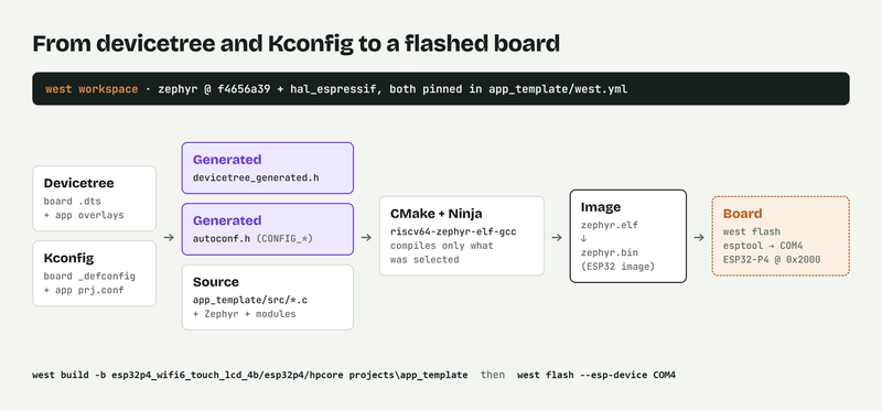
west build -p always -b esp32p4_wifi6_touch_lcd_4b/esp32p4/hpcore -d build\tmpl projects\app_template
The board target has three parts: board, SoC and CPU cluster. hpcore selects the ESP32-P4's pair of high-performance cores; the chip also has a low-power core, lpcore, which nothing here uses. -p always builds from scratch, and -d keeps each project in its own build folder.
Build Zephyr's own board first, if you have not yet. Swap the target for esp32p4_wifi6/esp32p4/hpcore and everything in this section and the two below works without a single file of your own. That proves the toolchain, the flash path and the console on their own, so a later failure has somewhere to point. The console output further down is from exactly that run.
Check these lines in the output:
-- Board: esp32p4_wifi6, qualifiers: esp32p4/hpcore
-- Found BOARD.dts: .../boards/waveshare/esp32p4_wifi6/esp32p4_wifi6_esp32p4_hpcore.dts
-- Found toolchain: zephyr 1.0.1 (.../zephyr-sdk-1.0.1)
-- Image partition address: 0x2000
Memory region         Used Size  Region Size  %age Used
           FLASH:      143748 B   33554176 B      0.43%
The board file it found — your own folder, or Zephyr's — the RISC-V toolchain it picked from the SDK, and the image size. For scale on this chip: stock hello_world is 142,032 bytes, and my application with shell, logging and a button library 243,328 bytes, in 32 MB of flash. The zephyr.elf beside it is about 3.2 MB, nearly all debug information that never reaches the board.
Flash
west flash -d build\tmpl --esp-device COM4
--esp-device COM4 is the serial port of the CH343 USB-to-UART bridge, the same port the console uses. Close any serial monitor first: Windows COM ports are exclusive, and a monitor holding the port makes the flash fail.
What lands on the chip is not the ELF file. There is no separate bootloader in this setup either: Zephyr's "simple boot" has esptool convert zephyr.elf into zephyr.bin, the format the chip's boot ROM understands, and the ROM loads it straight from flash offset 0x2000 — the address both the build and west flash print.
That offset is worth knowing, because the devicetree tells a different story at first glance: the ESP32-P4 partition table labels 0x2000 as mcuboot, then sys, then image-0 and image-1 for firmware updates. Under simple boot none of that applies. The image starts at 0x2000 and continues past those boundaries, so a 243 kB application covers the first three labels. The partitions that matter are the far ones, such as storage at 0x1FB0000, where settings or a file system belong.
Monitor
Any serial terminal at 115200 works. The one this project uses is miniterm, from the pyserial package already in the workspace:
python -m serial.tools.miniterm --filter direct --rts 0 --dtr 0 COM4 115200
Both flags earn their place. --filter direct stops miniterm's default filter from stripping terminal control codes, which is what turns Zephyr's coloured log lines into escape glyphs. --rts 0 --dtr 0 leaves the two handshake lines alone; on ESP boards they are wired to the chip's reset and boot pins, so a terminal that drives them resets the board as it opens, or drops it into the ROM bootloader. Ctrl+] exits.
Press the reset button, and the whole boot fits on one screen (trimmed, colour codes removed):
ESP-ROM:esp32p4-eco2-20240710
rst:0x1 (POWERON),boot:0x30f (SPI_FAST_FLASH_BOOT)
SHA-256 comparison failed:
Attempting to boot anyway...
I (soc_init): ESP Simple boot
W (boot): chip revision v1.0 is below the configured minimum v1.3
I (flash_init): SPI Flash Size : 32MB
I (boot): IROM : lma=00030000h vma=40000000h size=0c030h ( 49200)
*** Booting Zephyr OS build v4.4.0-16164-gf4656a39deb7 ***
[00:00:00.000,000] <inf> app_template: app_template on esp32p4_wifi6/esp32p4/hpcore
uart:~$ kernel version
Zephyr version 4.4.99
Three things to recognise in an ESP32-P4 boot log:
Everything down to
Attempting to boot anywaycomes from the chip's ROM, before any Zephyr code runs. The SHA-256 complaint is expected here, not a fault: a simple-boot image carries no appended digest for the ROM to compare against.Then Espressif's startup code inside Zephyr: the revision warning, flash size, and where each segment was loaded. The Zephyr banner after it names the exact commit the image was built from — keep it when you report a bug.
Your own log line and the shell prompt. The board target in that line is the proof: seeing your own board name means the image came from your folder and not from a leftover build.
If nothing appears, the likely causes are the wrong COM port, a monitor that was open during the flash, or console pins that do not match the schematic. If the board resets in a loop, build Zephyr's stock hello_world next, so your own code is out of the picture: copy the sample into your projects folder, give its CMakeLists.txt the same BOARD_ROOT line, and build it the same way. My own first boot on this panel was that sample, for exactly that reason:
W (boot): chip revision v1.0 is below the configured minimum v1.3
*** Booting Zephyr OS build v4.4.0-16164-gf4656a39deb7 ***
Hello World! esp32p4_wifi6_touch_lcd_4b/esp32p4/hpcore
A sample that boots while your application does not puts the fault in the application. A sample that fails too puts it in the board files.
What this bring-up does not cover
Eight files, console, GPIO and regulators — and nothing else. The 720×720 display, the touch controller, the microSD slot and the Wi-Fi link to the ESP32-C6 are all still dark. That is on purpose: every peripheral you switch on is another thing that can be wrong while you are still proving the basics. They come later in this series, one at a time, on a board that already boots reliably.
What's next
Part 5 leaves the hardware description behind and goes back to code: threads, timers and work queues, by building the heartbeat that this application logs every five seconds.
Resources
Zephyr's hardware model and board porting guide: docs.zephyrproject.org/latest/hardware/porting/board_porting.html
Devicetree bindings, what they are and how to write one: docs.zephyrproject.org/latest/build/dts/bindings.html
Espressif SoC support in Zephyr: github.com/zephyrproject-rtos/zephyr/tree/main/soc/espressif
Found a mistake or something unclear? Let me know in the comments below, and I will correct the post.