
Zephyr RTOS Architecture: How the Pieces Fit Together
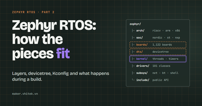
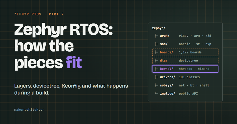
Zephyr RTOS, part 2. The layers that make up Zephyr, the two languages that describe a board and its features, and what happens when you type west build.
Part 1 called Zephyr more than a kernel. This post opens the box. Knowing where each piece lives pays off quickly: when a build fails or a peripheral stays silent, you know which layer to look at. The examples follow Zephyr's classic blinky sample on a Nordic nRF52840 DK, a board used in many Zephyr examples.
The big picture
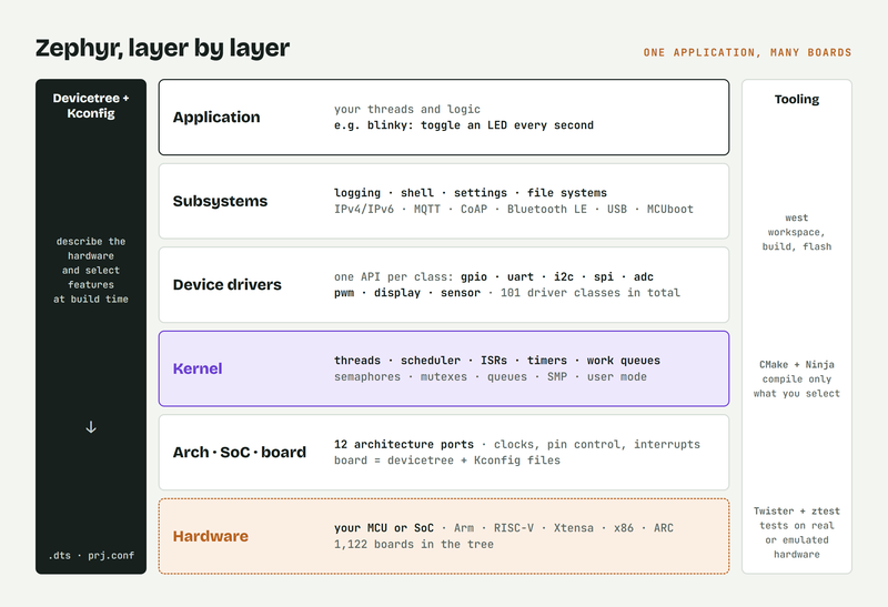
Zephyr is built in layers, and each layer uses the one below it through a defined interface. That is what lets the same application run on very different chips. From the bottom up:
Architecture, SoC and board
The lowest layer knows the hardware. An architecture port covers what all chips with the same CPU core have in common: reset and startup code, context switching, and interrupt entry and exit. Zephyr has 12 of them, including Arm, RISC-V and x86. The SoC layer adds what is specific to one chip family, such as clocks, caches, the memory map and boot requirements. The board describes the PCB: which pins go where, which LEDs and buttons exist, and which peripherals are switched on.
Kernel
The kernel schedules threads and provides the objects they use to work together: timers, work queues, semaphores, mutexes, message queues and more. Each thread has a priority. Cooperative threads keep the CPU until they block or yield; preemptible threads can be interrupted by more urgent ones. On multi-core chips the kernel can spread threads across cores (SMP), and on chips with memory protection hardware, threads can run in a restricted user mode.
Device drivers
Each class of peripheral has one API. Every GPIO driver implements the same GPIO interface, every UART driver the same UART interface, and so on across 101 driver classes. Your code calls the API; the driver for your chip does the work.
Subsystems
Above the drivers sit the services most products need: logging, the shell, settings storage, file systems, networking, Bluetooth, USB, power management and firmware updates. Each one is switched on separately, so you only pay for what you use.
Application
At the top is your code. In blinky, that is a loop in main() that toggles an LED once a second.
Tooling
Beside the layers sit the tools. west manages the source repositories and runs builds and flashing, CMake and Ninja do the actual build, and Twister with the ztest framework runs tests, both in simulation and on real hardware.
Where each piece lives
The Zephyr repository follows the same layers. Here is where to look, with the files that blinky uses on the nRF52840 DK:
Piece | Folder | For blinky on the nRF52840 DK |
|---|---|---|
Architecture port |
|
|
SoC support |
|
|
Boards |
|
|
Devicetree sources and bindings |
|
|
Kernel |
| the same for every chip |
Drivers |
|
|
Subsystems |
|
|
Public headers |
|
|
Samples |
|
|
Vendor HALs and other modules | next to Zephyr, fetched by west |
|
A board does not have to live inside Zephyr. An application can bring its own board folder and point the build at it with one line in its CMakeLists.txt. Part 4 of this series does exactly that.
Devicetree: the hardware, described
Zephyr borrows devicetree from Linux: a text format that lists the hardware, how it is wired and how it is configured. The SoC files describe everything inside the chip; the board file adds what is on the PCB. Here is part of the nRF52840 DK's board file, trimmed:
leds {
	compatible = "gpio-leds";

	led0: led_0 {
		gpios = <&gpio0 13 GPIO_ACTIVE_LOW>;
		label = "Green LED 0";
	};
	/* led_1 to led_3 follow the same pattern */
};

aliases {
	led0 = &led0;
	/* ... */
};
led0is an alias, a well-known name that samples look for. Any board that definesled0can runblinkyunchanged.gpios = <&gpio0 13 GPIO_ACTIVE_LOW>puts the LED on pin 13 of GPIO port 0 (P0.13). It is active low: the LED lights up when the pin is driven low.
Every compatible string, such as "gpio-leds", refers to a binding: a YAML file in dts/bindings/ (here dts/bindings/led/gpio-leds.yaml) that lists the properties a node may have and their types. The build checks the devicetree against the bindings and stops with an error when a required property is missing or a value has the wrong type.
The C code never mentions a pin number. blinky asks the devicetree for "the thing called led0":
#define LED0_NODE DT_ALIAS(led0)

static const struct gpio_dt_spec led = GPIO_DT_SPEC_GET(LED0_NODE, gpios);
At build time the devicetree becomes a C header full of macros, devicetree_generated.h, and this line compiles to a constant structure holding the GPIO controller, the pin number and the flags. Nothing is parsed at run time. Build the same code for another board with an led0 alias, and the line picks up that board's pin, controller and polarity.
Drivers: one API, many chips
With led in hand, blinky uses the generic GPIO API (trimmed):
if (!gpio_is_ready_dt(&led)) {
	return 0;
}

ret = gpio_pin_configure_dt(&led, GPIO_OUTPUT_ACTIVE);
/* ... */
while (1) {
	ret = gpio_pin_toggle_dt(&led);
	/* ... */
	k_msleep(SLEEP_TIME_MS);
}
Nothing here is specific to Nordic. gpio_is_ready_dt() checks that the driver started correctly at boot. Each of the other calls finds the driver's table of functions through the led.port device and calls the matching entry. For the nRF52840, that table is in drivers/gpio/gpio_nrfx.c:
static DEVICE_API(gpio, gpio_nrfx_drv_api_funcs) = {
	.pin_configure = gpio_nrfx_pin_configure,
	.port_get_raw = gpio_nrfx_port_get_raw,
	/* ... */
	.port_toggle_bits = gpio_nrfx_port_toggle_bits,
	/* ... */
};
On an STM32 board the same calls end up in drivers/gpio/gpio_stm32.c, and on a Raspberry Pi Pico in drivers/gpio/gpio_rpi_pico.c.
That is the device driver model in short. A driver creates a device for every enabled devicetree node with a matching compatible, the kernel initializes those devices during boot, and applications reach them through a pointer and a generic API. Moving an application to a new chip is mostly a question of whether a driver exists, not of rewriting the application.
Kconfig: the features, selected
The second language is Kconfig, the configuration system of the Linux kernel. Where devicetree describes hardware, Kconfig selects software: which subsystems, drivers and options are compiled in. Settings come in layers. The SoC and the board provide defaults (for this board in nrf52840dk_nrf52840_defconfig), and the application adds its own in prj.conf. For blinky, that is a single line:
CONFIG_GPIO=y
Adding features is just as short. These four lines give an application logging and a serial shell with kernel and GPIO commands, without a line of console code:
CONFIG_LOG=y
CONFIG_SHELL=y
CONFIG_KERNEL_SHELL=y
CONFIG_GPIO_SHELL=y
Kconfig also knows how options depend on each other. If prj.conf turns on an option whose dependencies are off, the build prints a warning that names the missing dependencies, and the option stays off. A misspelled option name is treated more strictly: it stops the build with an error.
Once a build folder exists, west build -t menuconfig opens a menu of every option, with its help text and dependencies (guiconfig is the graphical version). The final configuration ends up in two files in the build folder: zephyr/.config, which lists every option, and the header autoconf.h, which turns each enabled option into a CONFIG_... macro for the C code.
What happens when you run west build
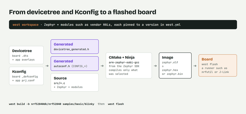
Two commands take blinky from source to a blinking LED:
west build -b nrf52840dk/nrf52840 samples/basic/blinky
west flash
west picks the target and calls CMake. The board target names the board and its SoC:
nrf52840dk/nrf52840. On multi-core chips it also names the CPU cluster, as innrf5340dk/nrf5340/cpuappfor the application core of an nRF5340.CMake configures the build. It merges the board's devicetree with any overlays and generates
devicetree_generated.h, then merges the Kconfig defaults withprj.confinto.configandautoconf.h. Mistakes in either are reported here, before any C file is compiled.Ninja compiles and links only what the configuration selected: the kernel, the enabled drivers and subsystems, the parts of the vendor HAL they need, and the application. The result is
zephyr.elf.Post-build steps convert the image into the formats flashing tools expect, such as
zephyr.hexandzephyr.bin.west flash hands the image to a runner, a small adapter for a flashing tool. For the nRF52840 DK the default is Nordic's
nrfutil, which programs the chip through the debug probe built into the board; J-Link, pyOCD and OpenOCD are set up as alternatives.
Putting it together
Zephyr is layered: architecture, SoC and board at the bottom, then the kernel, drivers and subsystems, with your application on top.
Devicetree describes the hardware; Kconfig selects the software.
Both become C headers at build time, so the compiler sees plain constants and builds only what you enabled.
west ties the workflow together: fetch the sources, build, flash and test.
What's next
Part 3 installs all of this on Windows: the host tools, west and the Zephyr SDK, ending with a first build.
Resources
Devicetree: docs.zephyrproject.org/latest/build/dts
Configuration system (Kconfig): docs.zephyrproject.org/latest/build/kconfig
Build system (CMake): docs.zephyrproject.org/latest/build/cmake
Device driver model: docs.zephyrproject.org/latest/kernel/drivers
Kernel services: docs.zephyrproject.org/latest/kernel/services
Found a mistake or something unclear? Let me know in the comments below, and I will correct the post.
Bình luận
Chưa có bình luận nào. Nếu bài này sai ở đâu, nói giúp.